ESSAY 5 - A COMPARATIVE ACOUSTICAL ANALYSIS OF THE RESPONSE AND TONE QUALITIES OF NINETEENTH CENTURY F TRUMPETS
As I have documented in the previous four essays, many nineteenth century observers found the tone quality of the long F trumpet to be superior to that of the high B-flat and C trumpets which eventually replaced them in the orchestras.[1] Even today, performers experience conductors who seem to lament the passing of the F trumpet and ask that the modern instrument be somehow played “more in the style” of the old F trumpets. Requests such as this put great pressure on orchestral trumpeters who have no idea what an F trumpet sounded like, much less how to adjust their playing to sound like one. Even in the absence of such professional demands, it may be of interest to many trumpeters and conductors to know how this extremely important instrument sounds and how that sound compares to the modern trumpet. To that end, the following essay compares the timbre, playing characteristics, and acoustics of a representative sample of nineteenth century F trumpets with modern orchestral trumpets.
Orchestral F trumpets were built by numerous makers in Europe during the nineteenth century and feature many different design and valve configurations. This study examines seven F trumpets built in Austria, France and England from the early, middle, and late nineteenth century. The Austrian instruments are rotary-valved trumpets marked Karl Frey of Amstetton and Anton Wild (Franz Streitwieser thinks it was probably also built by Frey). The English piston-valved trumpets are marked Boosey and Mahillion of London and the French piston-valved trumpets, Millereau, Silvani, and Courtois and Mille of Paris. These F trumpets were from the collections of Franz X. Streitwieser and Martin Lessen during the 1980s, and were graciously made available to me for the following tests. The Physics of Music Laboratory at the Department of Physics and Astronomy at the University of Rochester was chosen as the first test site and Dennis Fleisher, a Research Assistant in that department and an expert on trumpet acoustics, offered his services as technical advisor. Additional testing was later conducted at the Physics Department of Case Western Reserve University under the direct supervision of Dr. Arthur Benade, the world-renowned physicist, musician, and author of two books and numerous articles on musical instrument acoustics.[2] Two different testing procedures were applied; the first test established an input impedance curve for each instrument[3] and the second, a frequency spectrum analysis graph. Readers who are not particularly interested in the details of these test procedures may skip these sections and go straight to the Results sections that follow.
CHAPTER 1. INPUT IMPEDANCE TEST
The trumpet, like all wind instruments, is fundamentally a tube surrounding a column of air. The air column is set into vibration (excited) at the mouthpiece by the player’s buzzing lips. This vibration causes the column to resonate at frequencies determined by the length and shape of the tube. The air column of a trumpet, when excited, resonates at frequencies determined by its bore and length. On a good instrument, these frequencies are a close match to those of a harmonic series.[4] Certain modes of resonance (harmonics) on a given trumpet are stronger or more pronounced than others, and this tendency directly relates to the playing response of the instrument, the ease with which any given note can be played. Input impedance testing measures the strength of the natural modes available on a trumpet and displays the data as peaks on a graph.[5] Data obtained from this type of test gives information only on the air column, however, acoustical physicists have correlated this date with the perceived playing response of the trumpet, and that is what is be attempted here.
Input impedance testing procedures were developed by Earl Kent at C. G. Conn, Ltd., in Elkhart, Indiana, during the 1950s and improved by Arthur Benade in 1973[6] and John Backus in 1976.[7] Dennis Fleisher further improved these procedures for his own research on the trumpet receiver annulus. His work appears in his master’s thesis[8] from the Eastman School of Music and in an article published in the December, 1982, issue of the International Trumpet Guild Journal.[9] (see figure 1)

Figure 1. Dennis Fleisher with his impedance test apparatus at the University of Rochester. (c. 1983)
Test Procedure
Dennis Fleisher recommended the use of the “capillary excitation” procedure which was at that time, the most frequently employed method of testing input impedance.[10] The trumpet and mouthpiece are sealed to an apparatus which contains a transducer (microphone) and the end of a capillary tube attached to a loudspeaker driver. (See Figure 2) A pure sine wave tone produced by a variable frequency oscillator is employed to excite the speaker driver. A sinusoidal excitation provided by the driver travels down the capillary tube and excites the trumpet air column at the mouthpiece. The capillary tube acoustically isolates the driver from the trumpet. (See Figure 3) The oscillator creates a glissando, sweeping through all the frequencies from approximately 0 to 2,000 Hz. A standing wave forms in the trumpet’s air column when the oscillator frequency matches that of the resonant modes of the trumpet. As the excitation passes through the resonance frequency, the microphone in the mouthpiece cup measures the increased strength of the oscillating air pressure when the standing wave antinode becomes located at the mouthpiece, and records the resulting electrical voltage on the graph. As the oscillator frequency approaches a modal frequency of the air column, the voltage recorded on the graph rises in direct proportion to the pressure signal of the air in the mouthpiece. This is a measure of acoustical impedance.[11] The voltage peaks when a standing wave is established and impedance drops off again as the oscillator frequency continues past that of the instrument mode. Frequency is plotted using a logarithmic scale on the x axis of the data graph and voltage (impedance) on the y axis. The graphs in this chapter were produced in the laboratory using this procedure and are known as impedance or resonance curves.[12]


Figure 2. Completed mounting plate with mouthpiece, microphone and capillary.
Courtesy of Dennis Fleisher.

Figure 3. Schematic of acoustical impedance measuring apparatus as employed in this study. Oscilloscope connections not shown. Courtesy Dennis Fleisher.
The height of the impedance peaks represented on the graphs can be interpreted as evidence relating to the degree of playing responsiveness of the given frequency and its resultant note – i.e. the higher the peak, the more readily the trumpet responds to that note. Dr. Benade has determined that at a soft dynamic level, the player finds a note with a low impedance maxim (peak) “wobbly,” and that a taller peak produces a more stable note. Referring to a particular note exhibiting the highest peak on an impedance curve, Benade states, “…it proves to be one of the strongest and easiest notes to play on the trumpet.”[13] Impedance curves can therefore, be very useful in making direct comparisons between the relative responses of any number of instruments and these proved to be quite valuable in comparing nineteenth century F trumpets with each other, and with my modern Bach C trumpet.
Results of Tests
Examination of the impedance graphs in this chapter reveal differences in response between the various nineteenth century F trumpets; but more significantly, the results show marked differences between the nineteenth century F trumpets examined and my modern Bach 229 CL trumpet. My modern C trumpet shows a resonance peak on the fourth harmonic. (See Figure 4)
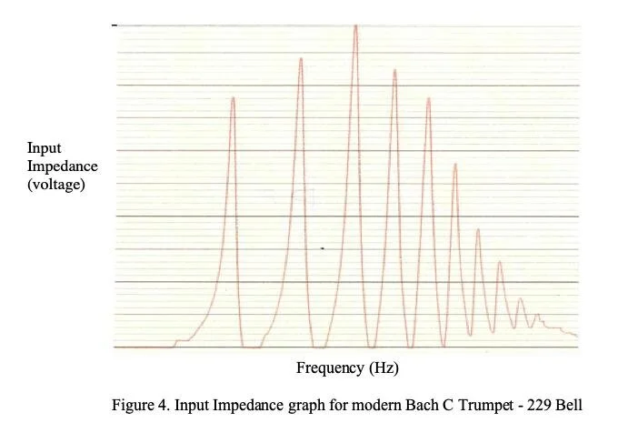
It must be noted that the fundamental is not represented on these graphs so the third peak represents the fourth harmonic. This peak corresponds to the note third space c" on the instrument. The impedance peaks for the F trumpets fall much higher in frequency, on either the seventh or eighth mode. (See Figure 5). These peaks correspond to concert e"-flat or f" which, when transposed for F trumpet, are notated as b"-flat or c" on the treble clef staff. The implications of this fact are significant. As has been previously stated, the height of the resonant peaks are directly proportional to the response of the instrument at that given frequency. Modern C trumpets play most consistently in their lower six modes and as might be expected, the graph in Figure 4 indicates that their strongest resonant modes are all in this area. When the performer on the C trumpet is forced to play in the modes above six, the instrument no longer adds its own resonance to the vibrations of the lips.[14] The result is often intonation problems and can result in missed notes. The most frequent criticism of the nineteenth century F trumpet involved just these types of playing problems.[15] Because of the lower pitch of the longer tube associated with the instrument, the player was forced to use the upper modes more frequently than on the high-pitched trumpets. This fact should result in less accurate playing. But the F trumpet impedance curves show that this problem should not have been as great as it is said to have been. These graphs show that the highest peaks occur right in the middle of the normal playing register of the F trumpet (see Figure 5). The F trumpet seems to have evolved so that it was able to play securely in the upper register and, in fact, performance testing bears this out.

Performance Testing
I tested the performance characteristics of the four F trumpets from the Streitwieser Collection by playing two excerpts from the orchestral repertoire on each. These excerpts were portions of Tchaikovsky’s Fourth Symphony and the high trumpet solo from Wagner’s Parsifal prelude. These excerpts were chosen because they were scored for F trumpet and they are frequently performed by modern orchestras. The objective was to subjectively determine if my performance impressions reflected the lab data described above.
The trumpet call at the beginning of Tchaikovsky’s Fourth Symphony is particularly exposed and one “crack” can ruin the entire effect. The high concert a"-flat must be attacked cleanly at a loud dynamic level and be perfectly in tune. This excerpt is difficult to perform accurately with a modern trumpet and I was prepared for a more difficult execution on the F trumpets. But I discovered that the F trumpets presented no serious problems in the accurate performance of this fanfare. The written e"-flat (played with the second and third valves rather than the second) was in tune and relatively secure. It was my impression that the F trumpets played the note almost as securely as my modern C trumpet, and with some practice might have eventually matched it in security.
The laboratory input impedance data supported this finding. The first note of the orchestral excerpt, the aforementioned high a"-flat on the C trumpet, corresponds to the seventh resonance mode or impedance peak on the graph of the C trumpet. This peak is pronounced, but quite low in intensity, and is located on the down side of the impedance curve. The same note is a written e"-flat for the F trumpets that corresponds to the tenth mode or impedance peak on the graphs for the F trumpets. Examination of the location of the tenth peak on the impedance curves indicates almost exactly the same configuration as the seventh mode on the C trumpet graphs - prominent, but of low intensity and found on the backside of the curve. In other words, both instruments should play this note with about equal “ease,” to quote Dr. Benade.[16]
The famous trumpet solo excerpt from Parsifal has been credited with forcing nineteenth century trumpeters to abandon the F trumpet in favor of the B-flat trumpet. If the nineteenth century criticism of upper-register playing was valid, this excerpt should be extremely difficult to play on the F trumpets. I found the F trumpets, however, proved to be only slightly less secure than my modern C trumpet for playing this excerpt. Both the modern C trumpet and the old F trumpets are required to play one resonance mode higher than in the previous example, however as was the case previously, the graphs of both types of instruments indicate a similar level of impedance, or “ease” of performance. One might conclude, at least from these subjective observations, that the F trumpet might NOT be as difficult to play accurately as has been reported. But what about the sound of these instruments? How does the timbre of the F trumpet, as measured by frequency spectrum analysis, compare with modern B-flat and C orchestral trumpets?
CHAPTER 2. FREQUENCY SPECTRUM ANALYSIS TEST
Hermann Helmholtz, the important nineteenth century German acoustical engineer, determined that instrument timbre (tone quality) results from the ear’s synthesis of a complex set of related vibrations or sound waves created in the air column of the instrument. The final wave form is created by the intersection of the individual wave forms of each harmonic present in the tone.[17] Therefore, when a note is sounded on the trumpet, the characteristic tone quality recognized by the ear is a combination of the fundamental frequency of the vibrating air column plus a number of other vibrations corresponding to the harmonics of the harmonic series of that note. This phenomenon is described by Dr. Benade: “A ‘regime of oscillation’ is that state of the collective motion of an air column in which… (the lips) collaborate with a set of air-column modes to maintain a steady oscillation containing several harmonically related frequency components, each with its own definite amplitude.”[18] It must be noted that a very soft note contains few additional harmonic vibrations of the fundamental, but the louder the dynamic level the more pronounced these harmonics become.[19] It is also of note that the wave form of the trumpet is such that some of these harmonic frequencies often exhibit higher amplitudes (relative strengths or loudness) than the fundamental itself.[20]
The tonal spectrum of a musical instrument is scientifically evaluated by measuring the relative strengths of all of the harmonics present in a given note at a steady sound level. This study is called frequency spectrum analysis. The physical characteristics which are measured in this way are perceived by the ear as tonal color or timbre. Helmholtz was not aware of it, but acoustical factors other than the pure sustained fundamental and its harmonics make up the tonal spectrum of a note played on the trumpet. These factors include: 1) Articulation – adding numerous new wave forms to the “regime of oscillation,” which quickly disappear from the tone after the attack; 2) decay – altering the regime as the note is released;[21] and 3) the room in which it is played – which can also create resonant frequencies at odds with those found in the steady tone spectrum.[22]
In fact, the room in which these tests were first conducted seemed to have had a negative effect on the spectrum analysis measurements recorded there. These early tests at the University of Rochester yielded results that were inconclusive because data from most of the instruments tested seems to have been affected by the resonance characteristics of the test room. Many of the spectrum graphs obtained at that time show the resonant effects of the room in ragged, saw-toothed curves reflecting sudden changes in dB measurements of individual harmonics.(See Figure 6) These graphs should exhibit a smooth slope downward and as we shall see later, the graphs obtained using the “room average” technique do show this more graduated slope.(See Figures 6 & 8) A comparison of the graphs of the Courtois & Mille trumpet tested by both procedures shows the effect of the room on the first procedure and the “room average” measurement obtained using the second procedure.

Figure 6. Spectrum Analysis graph made from data obtained at Rochester. Note the ragged sawtooth pattern of the respective curves.
Benade’s “Room-Average” Test Procedure

Figure 7. Dr. Arthur Benade at Case Western University with Hewlett-Packard 3582A real-time spectrum analyzer.
It was at this point that I sought the assistance of Dr. Benade (1925 - 1987), Professor of Physics at Case Western University. He agreed to assist me with this study and recommended a test procedure which he was developing at the time that effectively eliminates the resonant effect of the room in which the tests are made. His “room-average” test procedure was employed for this study and produced much better data. [23]The essence of Dr. Benade’s technique is as follows:
1. The test is conducted in a large, resonant room (concert halls are fine).
2. The player and the microphone should be separated by some distance and be well away from any walls or other reflecting surfaces.
3. The player plays a single note at a mezzo forte dynamic level and sustains it as long as possible. The use of a sound-level meter is unnecessary.
4. While the note is being sounded, the player is instructed to walk slowly around the room.
5. While the note is being sounded, the microphone must also be carried around the room at arm’s length and pointed in all directions, but avoiding pointing directly at the trumpet.
6. The resulting tone can then be recorded for later study or fed directly into the Hewlett-Packard 3582A real-time spectrum analyzer for instant readout.
This procedure was employed at the Streitwieser Historic Trumpet Museum in November of 1983, with the assistance of Franz Streitwieser. The instruments tested were the two rotary-valved F trumpets built by Karl Frey, an unsigned rotary-valved F trumpet, and piston-valved F trumpets built by Heinem, Boosey, and Courtois and Mille. By way of comparison, two modern C trumpets were tested, my Bach LC, 229 bell, and a Bach MLC with a 239 bell. And finally, two B-flat trumpets were also tested, a modern Bach “Stradivarius,” Model 37, and an early twentieth century rotary-valved F. A. Heckel built in Germany. An electrovoice RE55 Dynamic omni-directional microphone and a Techniques cassette deck were employed for the recording. The tape was later analyzed at Dr. Benade’s laboratory at Case Western Reserve employing the afore-mentioned Hewlett-Packard 3582A real-time spectrum analyzer.
Results of the “Room-Average” Test Procedure
The dB level for each harmonic represented in the spectrum for each instrument tested was plotted on a graph. The points were then connected by a line to show the shape of the spectrum slope for each trumpet.(See Figure 8)

Figure 8. Spectrum Analysis graph of six F trumpets made from data obtained by employing the “room-average” measurement technique at Case Western Reserve University.
Examination of the F trumpet graph reveals very distinct similarities in spectrum between all of the instruments tested. This is significant because my playing tests clearly revealed a distinct similarity in timbre between the F trumpets as a group, and this test procedure offers empirical evidence confirming my aural perception. Of greatest interest is the fact that, with the exception of the unsigned F trumpet, all of the instruments tested produced almost even dB levels for the fundamental and the next two harmonics. These readings never deviated more than three dB above or two dB below the designation for the fundamental.
The twentieth century high-pitched trumpets as a group, revealed more variation in spectrum from instrument to instrument.(See Figure 9) The three Bach trumpets tested produced the most consistent data, as might be expected, but the rotary-valved Heckel B-flat trumpet produced a very different curve.

Figure 9. Spectrum Analysis graph made from data obtained by employing the room-average measurement technique at Case Western Reserve University with high-pitched trumpets
All of the high trumpets produced a graph with one obvious similarity – the fundamental recorded a relatively weak dB level as compared to the second and third harmonics. The modern Bach trumpets, in particular, produced curves which exhibited second and third harmonics which ranged from a minimum of three dB to a maximum of nine dB above the fundamental. These graphs are accurate to plus or minus 1.5 dB, so this observation is quite significant. The Heckel trumpet follows this trend for the second harmonic, but drops off rapidly from that point.
This phenomenon can be seen from a different perspective by comparing both of these charts with each other. (See Figures 8 & 9) The slope and dB levels of both groups of instruments are quite similar. The greatest difference is seen in the relative dB levels of the fundamentals. The fundamentals of the high-pitched trumpets are approximately five dB lower than that of the F trumpets as a group, which can be interpreted as an indication of a relatively lower power level. The reader my recall criticism of the high-pitched trumpets from the turn of the twentieth century mentioned in Essay 3 of the historical portion of these essays. Richard Hofmann, writing in Leipzig in 1903 stated that the shorter or higher trumpets lacked the “power” of the lower-pitched instruments.[24] This data seems to support his observation over a century later.
One final observation notes the striking similarities that exist between the graph of the rotary-valved F. A. Heckel B-flat trumpet and that of the F trumpets. (See Figures 8 & 9) My subjective impression confirmed that the timbre of rotary-valved B-flat trumpet was in fact, more like that of the F trumpets than the modern piston-valved Bach trumpets. And many orchestral trumpeters here in America now employ rotary-valved trumpets for the performance of music by certain Romantic period composers. This data appears to justify this practice. However, a word of caution from Franz Streitwieser; he states that there is general agreement among European trumpeters that modern rotary-valved trumpets are “not as good” as those built by F. A. Heckel early in the twentieth century, and the specimen that was tested here dates from that era.
Conclusions
The spectrum analysis data presented here shows clear differences in the two groups of trumpets tested, the F trumpets and the high-pitched B-flat and C trumpets. Arthur Benade, however, made it clear to me that scientific understanding of exactly how spectrum graphs reflect instrument timbre is incomplete. Acoustical physicists who deal with musical instrument spectrum analysis have discovered that the best test procedures do not always produce data that reflects what is clearly audible to the listener. Because of this fact, Dr. Benade suggested that no attempt be made to correlate the specific data obtained during this study with specific aurally perceived timbral characteristics of the trumpets tested, other than those of a most general nature. It is hoped that further study and better instrumentation will eventually allow scientists and musicians to more accurately interpret the specific events on a spectrum graph and relate them directly to a perceived timbral quality. We are fortunate in this case that the graphic data so clearly delineated the F trumpets as a group from the modern high-pitched trumpets.
[1] Walter Morrow, “The Trumpet as an Orchestral Instrument,” The Proceedings of the Musical Association, Vol. XXI, (1894-1895), p. 139.
[2] Arthur H. Benade, Fundamentals of Musical Acoustics, (New York: Oxford University Press, 1976), p. 396.
[3] Dennis Fleisher, An Acoustical Study of the Trumpet Receiver Annulus. MA Thesis: Eastman School of Music, 1980.
[4] Arthur Benade, Interview with the author (May, 1983).
[5] Arthur H. Benade, “The Physics of Brasses,” Scientific American, Vol. CCXXIX, (1973), p. 29.
[6] Ibid. p. 28.
[7] John Backus and T. C. Hudley, “Harmonic Generation in the Trumpet,” Journal of the Acoustical Society of America, Vol. LXL, (1971), p. 509.
[8] Fleisher, op. cit.
[9] Dennis Fleisher, “The Trumpet Receiver Gap: An Acoustical Study,” The International Trumpet Guild Journal, Vol. VII, No. 3, (1982).
[10] Fleisher, Thesis, op. cit., p. 80.
[11] Benade, “The Physics of Brasses, op. cit., p. 28.
[12] Fleisher, op. cit., pp. 80-87.
[13] Benade, Fundamentals, op. cit. p. 403.
[14] Ibid, p. 404.
[15] J. Fétis, A Manual for Composers, translated by Wellington Guerney, (London: Duncan Davison & Co.), p. 26.
[16] Benade, op. cit., p. 403.
[17] Hermann C. F. Helmholtz, On the Sensations of Tone as a Physiological Basis for the Theory of Music, translated by Alexander J. Ellis, third edition, (London: Longmans, Green & Co., 1895).
[18] Benade, op. cit., p. 395.
[19] Ibid, p. 402.
[20] Backus op. cit., p. 509.
[21] Kenneth W. Gerger, “Some Factors in the Recognition of Timbre,” Journal of the Acoustical Society of America, Vol. XXXVI, No. 10, (1964), p. 1898.
[22] E. L. Saldanha & John F Corso, “Timbre Cues and Identification of Musical Instruments,” Journal of the Acoustical Society of America, Vol. XXXVI, No. 11, (1964), p. 2021.
[23] Arthur H. Benade, “WIND INSTRUMENTS IN THE CONCERT HALL,” A talk given at the Parc de La Villette, Paris, 15 May 1984, https://ccrma.stanford.edu/marl/Benade/writings/Benade-Villette1984.html
[24] Richard Hofmann, Die Musikinstrumente ihre Beschreibung und Verwendung, (Leipzig: J. J. Weber, 1903), p. 188.